Fjernsupport
Studerende
Log ind
Book møde

PCB Design

PCB Design Solutions

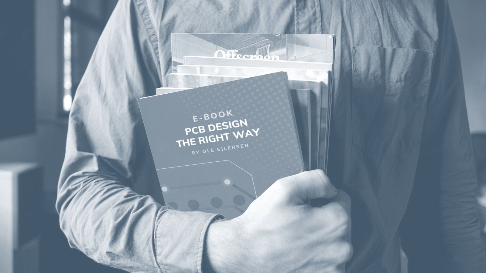
We understand that every design challenge is unique. That’s why your PCB design tools should be flexible, customizable and scaleable. Our tools don’t just solve your immediate problems—they help you design with confidence, stay competitive, and focus on what you do best: innovating.

Free yourself from rigid and limiting software to maximize productivity, collaborate seamlessly, and meet time-to-market with ease - everytime.

PCB design

Unlock effortless PCB design with tools that solve your everyday challenges

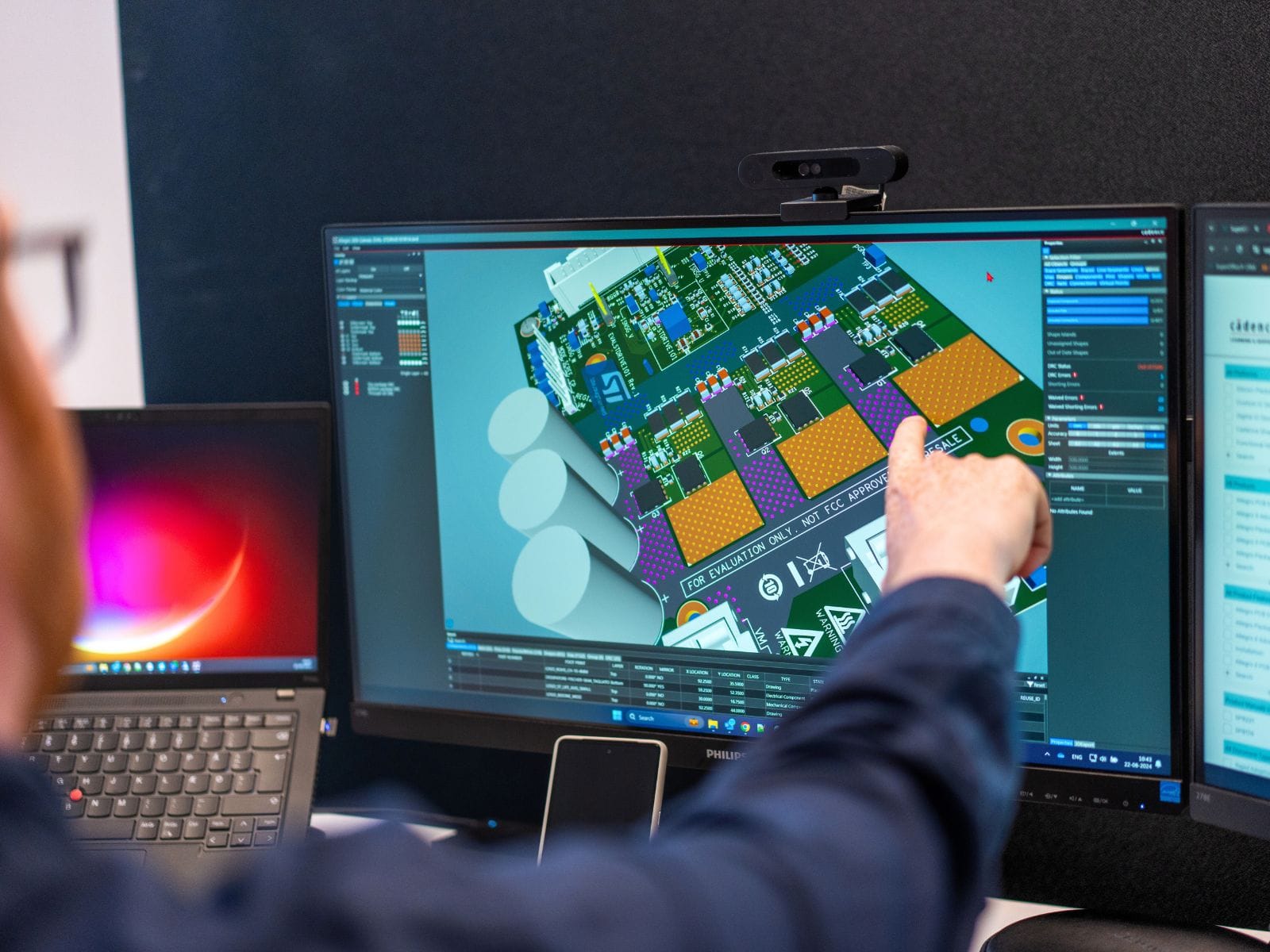
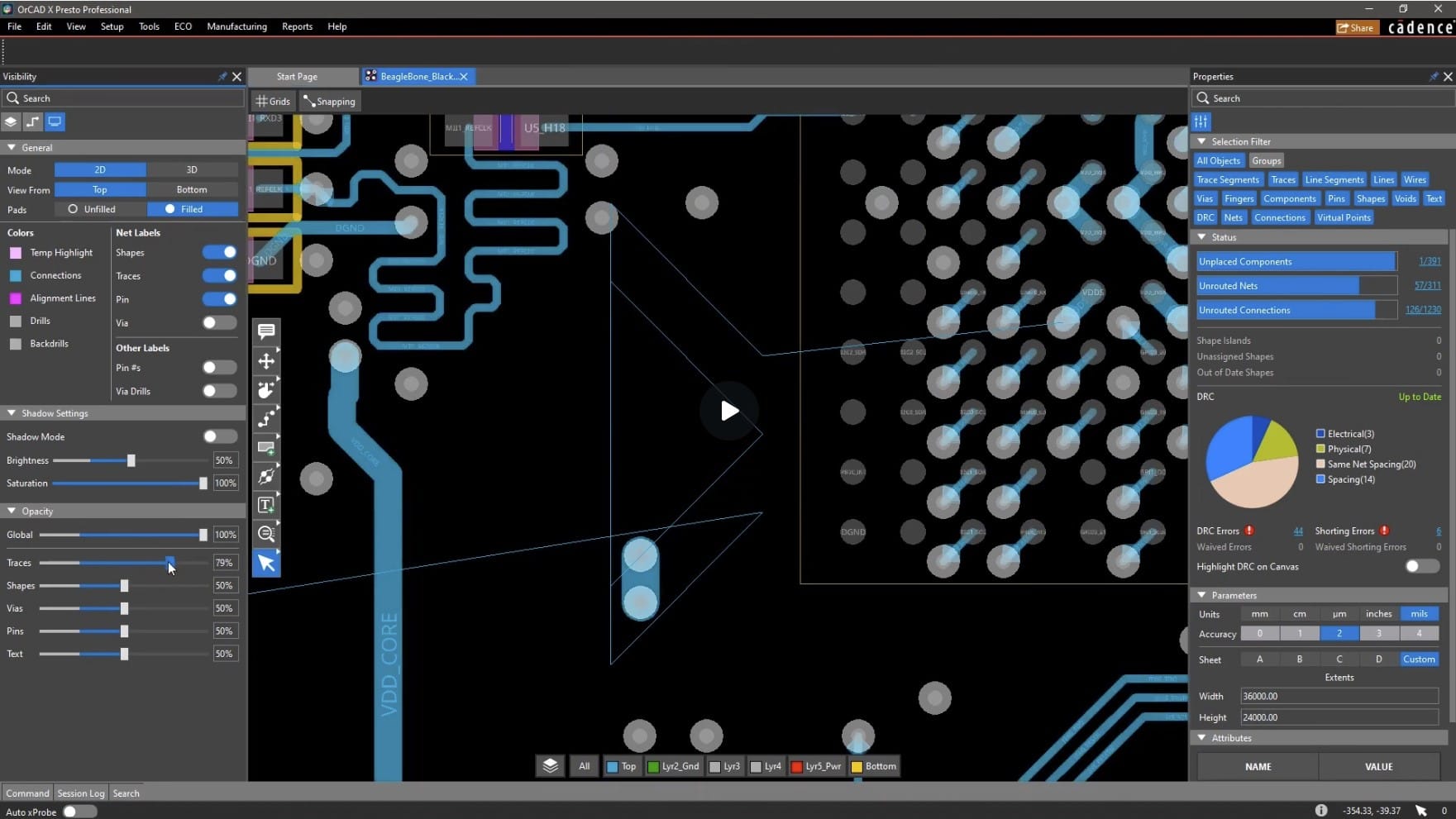
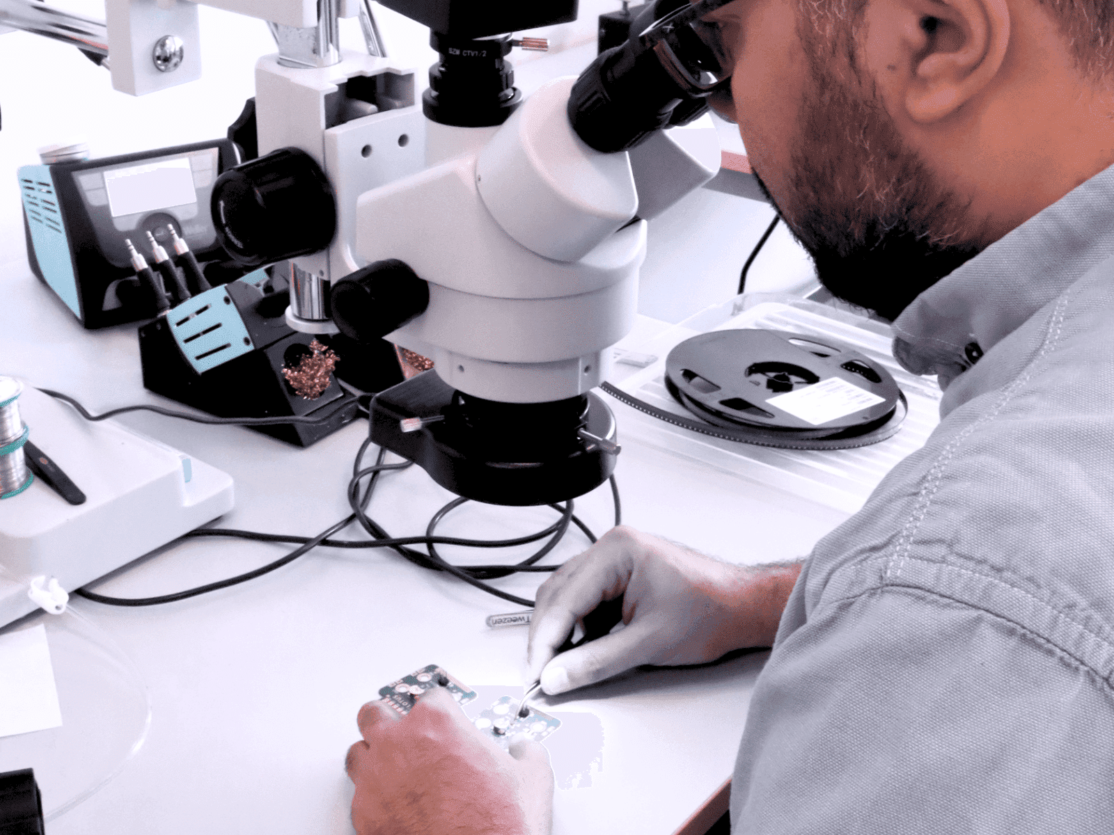
Are you tired of running into the same design issues, project delays, and costly errors? With growing complexity and shrinking timelines, designing a high-performance PCB can feel like an uphill battle.

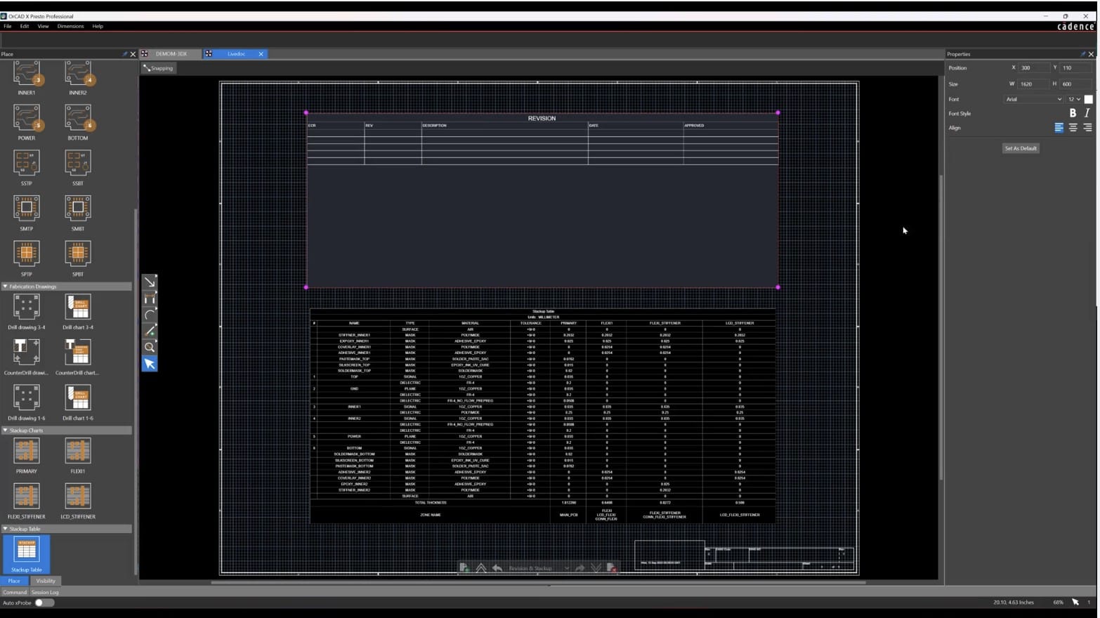
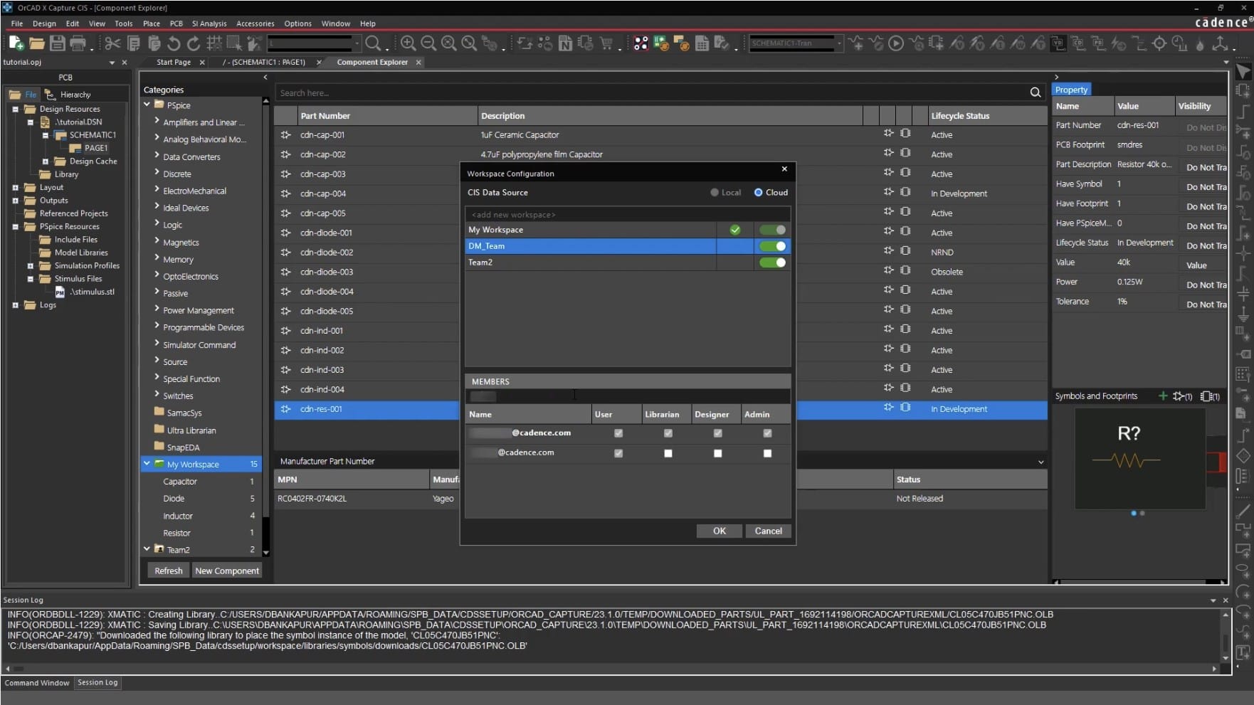
Our PCB design solutions are engineered to tackle these exact challenges head-on, so you can focus on innovation instead of troubleshooting. From intuitive design tools to advanced simulation and error checking, we give you everything you need to create reliable, manufacturable PCBs—faster than ever before.

Watch the video to see the latest OrCAD X interface in action.

Take control of your design process

Layout design
Design verification
Integrated collaboration

Make complex designs feel simple

PCB layout design often feels like balancing complexity and speed. With our powerful layout tool, you can streamline the process and eliminate the guesswork. 

From automated rule management to advanced routing capabilities, we help you stay in control while delivering accurate, high-quality designs.
Constraint management across schematic, layout and analysis
Integrated SPICE analysis 
Automated component placement, power plane creation and signal routing
Challenge
Solution
Complex design rules can be hard to manage and enforce, leading to potential errors.
Set up and manage your design constraints quickly within an intuitive spreadsheet-based interface. Real-time verification ensures that every design rule is met as you work, ensuring designs comply with specifications as you go.
Repetitive tasks slow down your progress and increase the risk of errors.
No need to reinvent the wheel. Leverage proven design IP to replicate circuits and reuse components across projects, saving you hours of effort and minimizing the risk of error.
Signal routing challenges can cause delays and performance issues.
Meet your design specifications with ease. Whether you’re optimizing signal lengths or routing for minimal interference, our intelligent place and route tools give you visual cues and interactive checks to ensure every trace meets your goals.
Lack of design visualization can lead to unexpected physical fit problems.
Visualize your rigid-flex designs in 3D and ensure they fit perfectly in real-world applications. Detect part collisions and optimize flex areas before production to avoid costly mistakes.

Reduce risks, boost reliability

PCB designs must be flawless, both for performance and manufacturability. Our design verification tools ensure your boards meet stringent industry standards before they reach production, allowing you to catch and resolve issues early in the process.

You'll gain:
Automatic detection of impedance discontinuities and signal coupling issues in real time—no guesswork required.
Guaranteed manufacturability with in-design DFM rules covering assembly, fabrication, and testing.
Effortless documentation with pre-configured templates that auto-populate from your source layout, so you can minimize the risk of documentation errors.
Challenge
Solution
Signal integrity issues are difficult to identify without time-consuming simulations.
Automatically detect impedance and coupling issues early, with no need for complex simulations or expert knowledge.
Manufacturability concerns can lead to production delays or costly errors.
Apply in-design DFM rules to ensure your board is ready for assembly, fabrication, and testing—preventing costly rework down the line.
Manual documentation processes are time-consuming and prone to errors.
Use pre-built templates that auto-populate from your layout, ensuring accurate and up-to-date documentation every time.

Design as a team, anywhere

Collaborating effectively across teams is crucial for keeping projects on track. Our integrated collaboration tools enable your team to work together, whether they’re in the same office or across continents.

You'll gain:
Efficient design reviews where you can provide feedback, annotate designs, and leave comments directly in the layou. This eliminates the need for endless email chains and long approval processes.
Seamless ECAD/MCAD integration which ensures that your electrical and mechanical teams can share updates instantly
Real-time co-design: where you don’t need to wait for feedback—work with your team on the same project at the same time from anywhere.
Challenge
Solution
Slow design feedback processes cause delays and missed communication.
Annotate and leave feedback directly in the layout, streamlining communication and speeding up revisions.
Disjointed communication between electrical and mechanical teams leads to design misalignment.
Collaborate seamlessly in real time, ensuring design changes are instantly reflected across both teams.
Asynchronous design processes slow down project timelines.
Work concurrently with teammates in the same design database, accelerating the design process and reducing time to market.

You will maximize your ROI with Nordcad

But don't take our word for it. Take it from our customers.
Experiencing a large growth, we were more and more exposed to the risk of mixing up BOM’s for all our parts and variants. We realised that Excel could no longer give us the level of confidence that we needed, and searched the market for a solution. Highstage has proven great in getting a strong grip on our BOM’s and revision control.
Joakim Jørgensen
Hardware Developer at Develco
Uneeg uses Highstage across their development projects. Documents are electronically signed by reviewers and approvers, according to FDA CFR Part 11 requirements. Nita Volder Hansen – Process Engineer at Uneeg – is a big fan of references, and for a good reason – references in Highstage are used to manage which revision is correct and valid. Using the Reference Lock functionality, a revision can be locked to the DHF even if newer versions exist.
Nita Volder Hansen
Process Engineer at Uneeg
Highstage has significantly enhanced production efficiency while minimising errors. Thanks to the persistent links that consistently display up-to-date revisions of drawings and production documents, Highstage has brought about a singular, reliable source of truth.
Christopher Grinde
Head of Sensor Development, Nortek
Danfoss
We quickly realized that there were many low-hanging fruits we could pick to streamline the process. Nordcad has been responsive to our needs and very skilled in delivery. They have also helped automate output, ensuring consistent results every time.
Torsten Larsen
Torsten Larsen, Global ECAD Solution Owner
Lotus Microsystems
The flexibility of OrCAD caters to businesses of all sizes and offers tailored package solutions to meet various needs. The inclusion of Nordcad's support is invaluable and provides quick assistance.
Sebastian Tengvall
Application Engineer, Lotus Microsystems

Our PCB design solutions

Whether you are a one-person team or a team member in cooperate - we have a solution for you.
OrCAD X, features, schematic, PCB Design
OrCAD X
For every user
Presto PCB Editor
LiveDOC
Review and markup
3DX canvas
DFM (Design for Manufacturing) checks
Cloud services
Rigid-Flex design
See plans and features for OrCAD
OrCAD X, features, schematic, PCB Design
Allegro X
Best suited for enterprises, for special options and RF routing
3D handling
Special routing
DFA (Design for Assembly)
Electrical rules (Reflection, timing, crosstalk)
LiveBOM
Signal Integrity checks
AWR Microwave Office interface
See plans and features for Allegro X

Powering 300+ Nordic companies with the best EDA solutions

Resources

Webinar

The complete OrCAD X tour

Watch the webinar →

E-book

The A- Z guide to PCB Design

Read the e-book →

Article

Test vs. simulation

Read the article →
Copyright © 2025 Nordcad Systems A/S
userscrosscheckmark-circlechevron-right-circlelayers