


Key takeaways from this article:
- How to get the input data for thermal simulations.
- Which measurements to gather in the design.
- How the data is used in setting up a thermal simulation.
Let's paint a picture here. Imagine you've got a system that's running hotter than it should, and you need to evaluate your options regarding cooling solutions, such as fan or liquid cooling. In simulation, any cooling can be evaluated, but how do you make sure it accurately reflects reality, defining the sources and boundary conditions in the simulation model?
To get the right data for thermal simulations, you need to understand the main heat contributors in the system. That means rolling up your sleeves and taking some measurements with a prototype so you can plug in the right info for your simulation model. When you're dealing with electronic systems, you usually rely on methods like thermocouples or infrared cameras to figure out where the heat's coming from.
Once you know the key factors, you can start simulating the system, making sure to use your measurement data correctly. We'll dive into the nitty-gritty of what measurements you need to collect during the design phase and how to put them to work when setting up your thermal simulation.
Begin with thermal measurements
It all begins with getting the right measurements and mapping out the scenario you're aiming to recreate in the simulation. In thermal simulations, the aim is to crunch the numbers and figure out how the temperature is distributed across the given heat sources within the system. Plus, you'll need to figure out the required time for changes to happen when the system is affected, for example, by introducing some airflow.
With an initial temperature distribution simulation, you've got yourself a solid foundation that can be used to start evaluating redesigns, such as adding a fan into the system.
Define the requirements
Before diving into temperature measurements, it's crucial to have a clear picture of what you're comparing them to. Think of it like setting the stage for a play—before the actors come in, you need to know the setting, the props, and the storyline. Here are some key decisions you'll need to make for your test case:
- How much power are the crucial components consuming?
- Are you including any thermal gap pads or heat sinks?
- Once the modifications are made, can you reliably reproduce the measurements?
These may seem like simple steps, but they're the bread and butter of setting up thermal test cases for a product. Typically, you'll analyze two main scenarios: standard operating conditions and stressed operating conditions. Standard conditions reflect the everyday use of the product, while stressed conditions push it to the brink, testing its limits and susceptibility to failure.
Where to take measurements
When measuring temperatures within a system, focusing on a few critical areas is essential to get the full picture of how the heat is distributed throughout the product. Here are the main ways you can gather temperature measurements:
- Point measurements with thermocouples: They are like the precision scalpels of temperature measurement. They give you a reading at a specific point in the system, allowing for detailed insights.
- Point measurements with an infrared thermal sensor: Think of these as your point-and-shoot cameras for temperature. They give you instant readings at a specific spot, but like thermal cameras, they need the enclosure to be fully open to get readings from the PCB.
- Complete system measurements with a thermal camera: Thermal cameras capture the temperature distribution across the entire system, providing a comprehensive snapshot of what's going on.
While infrared sensors and thermal cameras have their perks, point measurements with thermocouples are often the gold standard. Why? Because they can be wired into a closed package and directly attached to an IC package, giving you precise temperature readings without needing to expose the system.
When using a group of thermocouples, you should take measurements directly on all of the hot IC packages, because these packages are the dominant heat generators within the system. Plus, you can use these measurements later to determine the materials data needed in the thermal simulation.
And don't forget the empty space, when it comes to temperature even the air in your design matters. Take a temperature reading of the stagnant air inside the enclosure. It might seem irrelevant, but it's crucial for evaluating your simulation model.
Finally, place a thermocouple on the surface of the enclosure or measure the enclosure temperature with a thermal camera.
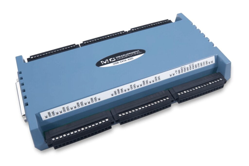
And guess what? You don't need any high-tech equipment for this. These direct measurements can be done with an off-the-shelf DAQ unit, such as the trusty Measurement Computing unit shown below.
Once thermocouples are installed, it's essential to monitor the design's behavior over time to observe its approach to composure. Once the system reaches the equilibrium temperature, the DAQ system will continuously record measurements at each designated point in the system.
In certain situations, obtaining all these measurements can pose challenges, particularly when dealing with enclosures that have a low profile and lack open access points for thermocouples. In such cases, opening the enclosure and placing the PCB within a slightly larger container may be necessary to accommodate the thermocouples. Alternatively, utilizing a thermal camera for direct imaging can bypass the need for point measurements with thermocouples, providing surface temperature readings directly from the primary heat-producing components.
Recreate Measurements in Simulation
Before analyzing changes to a design in a simulation, it's crucial to utilize existing data to replicate your current measurements in the simulation environment. This recreation of the test case serves as a validation step for your simulation model, with the physical test case serving as a reference point against which simulation results are benchmarked.
Thermal simulations necessitate solving the heat equation within a closed system, which in turn requires knowledge of thermal conductivity at various system points. While integrated circuit packages don't typically provide this data in the same manner as enclosure or PCB materials, it can be derived from the package's thermal resistance value in its datasheet and direct temperature measurements during operation.
To predict the steady-state temperature distribution within the product, a thermal simulation relies on a value for the heat source (S). The provided image outlines the necessary inputs for an integrated circuit simulation package to calculate the heat flux originating from the source (S):
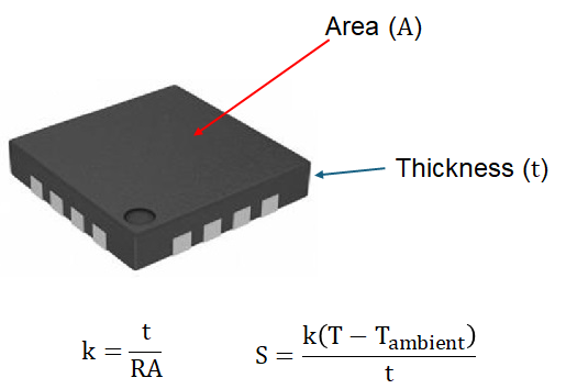
The value assigned to T(ambient) serves as the starting point for the stagnant air within the enclosure. As for the other temperature value (T), it can be regarded as a static figure for defining a heat source within the simulation. To keep things simple, setting T equal to your package temperature measurement at equilibrium suffices.
Armed with the determined package thermal conductivity (k) and the static package temperature (T), you're all set to configure a transient thermal simulation with the following parameters:
- Initial conditions:
- T(ambient) known, allowed to change
- The temperature of the enclosure body (can be set to T(ambient))
- Boundary conditions:
- T known from measurement, set as a static value
- Temperature outside the enclosure (typically room temperature)
Alternatively, you can set up a steady-state thermal simulation by utilizing T(ambient) as the stagnant air temperature and the enclosure temperature recorded during thermal equilibrium. These simulations are quicker and provide robust validation for your system's simulation model.

Modify the System and Re-simulate
Once you've wrapped up the simulation and gathered the reference data, it's time to roll out the proposed modifications and give the system another once-over. If feasible, this phase can be coupled with fresh measurements. However, it's not always an option in every scenario. Regardless, simulations offer the speediest route to start vetting design changes to mitigate thermal load.
Take, for instance, the qualified simulation model used to replicate thermocouple measurements. You can tweak this model to introduce a fan. Through CFD-thermal co-simulation, you can inject an airflow source and run a transient simulation to scrutinize how different flow rates impact equilibrium temperature during operation. This approach enables you to swiftly pinpoint potential issues that might prove elusive through measurements alone, such as:
- Hot spots with stagnant air
- Areas with low flow
- How inlet and exhaust placement affect airflow
- How the above points impact enclosure surface temperature
- How great is the temperature decrease as a function of airflow
- Exhaust air temperature
Some of these aspects can be directly visualized on the board surface, akin to typical thermal simulations, but with added streamlines to delineate airflow distribution. Other cooling strategies like employing heat sinks, attaching thermal interface materials to the enclosure, or exploring larger enclosure dimensions can also undergo scrutiny in these simulations.

While the initial legwork of gathering thermal data for simulation purposes may be time-intensive, it lays the groundwork for a design team to swiftly vet design alterations about thermal control and management. This, in turn, slashes the need for additional prototype iterations, saving both time and money. Moreover, the simulation model remains adaptable, allowing for continuous refinement as new prototypes are fabricated for testing. Growing design teams can quickly see ROI by adding this capability to their suite of design tools.
Celsius EC Solver is a powerful tool powered by a strong computational engine and meshing technology. It enables engineers to model and analyze complex designs to reduce the risks of product failures and optimize thermal solutions to maximize performance.
It delves into fluid flow and heat transfer dynamics within diverse electronics systems. Its proprietary multi-level unstructured meshing technology ensures precision and efficiency from addressing convection and conduction to radiation.
The benefits of using a tool like Celsius EC Solver:
- Addresses thermal/electronics cooling challenges in the earliest stages of a design
- Reduces costly design respins and engineering delays
- Improves product performance and reliability
- Scales to hundreds of cores for addressing high-complexity systems
It's a great solution for analyzing airflow, temperature profiles, and heat transfer across various electronic components, enclosures, and power systems. It offers insights into natural and forced convection, solar heating, and liquid cooling, giving you the tools to make informed decisions.