In turbomachinery, even small inefficiencies can translate into significant energy losses. One of the most critical — and often underestimated — sources of aerodynamic loss is secondary flow, a complex three‑dimensional phenomenon that can account for up to 50% of total losses in axial turbines.
Secondary flows occur when pressure differences across turbine blades drive fluid from the pressure side to the suction side, creating vortices that disrupt the main flow. These vortical structures — including horseshoe vortices (HSV), passage vortices (PV), and tip‑leakage vortices (TLV) — distort the velocity field, reduce efficiency, and increase mechanical stress on turbine components.
Understanding, predicting, and mitigating these effects is essential to achieving higher efficiency, reliability, and durability in modern turbines.
This e‑book explores how Cadence Fidelity CFD and Fidelity Turbo enable engineers to accurately simulate and minimize flow losses in complex turbomachinery systems.
Using a 1.5‑stage Aachen axial turbine as a reference case, the study demonstrates how Fidelity Turbo’s end‑to‑end workflow — from geometry definition and automated meshing to advanced post‑processing — provides deep insight into the flow field. The software supports multistage axial, radial, and mixed‑flow turbines, as well as compressors, pumps, and propellers, making it a versatile solution for any turbomachinery application.
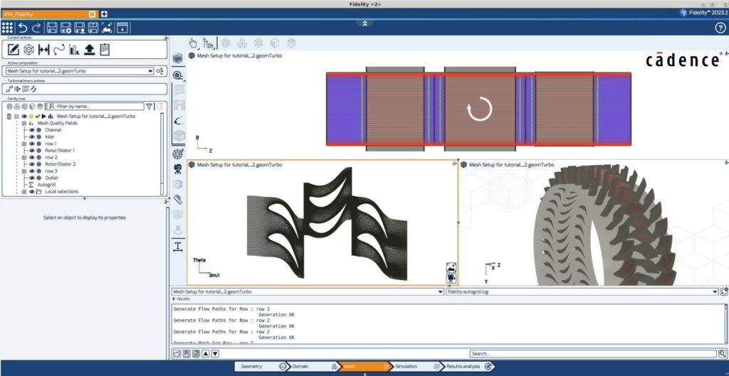
Through automated meshing with Fidelity Automesh, engineers can generate high‑quality structured or unstructured grids in seconds, ensuring accurate resolution of flow features such as boundary layers, wakes, and vortices. This process enables rapid iteration and design exploration without sacrificing precision.
The e‑book details how flow structures develop across the turbine’s stator and rotor stages. The pressure difference between the blade’s sides drives fluid transversely, while boundary layer effects near the endwalls introduce low‑momentum zones that feed vortex formation.
Key flow features include:
By visualizing these structures through velocity contour plots and iso‑velocity lines, engineers can identify regions of steep velocity gradients and flow separation — the primary sources of aerodynamic inefficiency.
With Fidelity Turbo, design teams can explore strategies to suppress secondary flow formation and recover lost energy. Techniques such as endwall contouring, blade profile optimization, and tip‑clearance reduction can be modeled and validated virtually before physical testing.
The simulation results from the Aachen turbine study show that adjusting the blade‑tip geometry and endwall design helps redirect flow, reduce vortex strength, and achieve more uniform velocity distribution across the turbine passage.
This simulation‑driven approach transforms secondary flow from a loss mechanism into an opportunity for aerodynamic improvement — turning losses into gains.
Fidelity Turbo supports a range of turbulence models — from Reynolds‑Averaged Navier‑Stokes (RANS) to Large Eddy Simulation (LES) — allowing engineers to balance computational cost and fidelity.
In the Aachen turbine case, the Spalart‑Allmaras model was used to efficiently capture key flow features, while Fidelity’s LES solver offers even higher accuracy for unsteady vortex dynamics. These models ensure that flow interactions are faithfully represented, enabling engineers to make confident design decisions.