


Table of Contents
Creating accurate CFD meshes for complex marine geometries is one of the biggest challenges facing naval architects and marine engineers today. Ships, offshore platforms, and underwater vehicles have intricate shapes with curved surfaces, sharp edges, and multiple components that make mesh generation extremely difficult and time-consuming.
The quality of your CFD mesh directly determines the accuracy of your simulation results, making proper meshing techniques essential for reliable marine design analysis. Poor mesh quality can lead to convergence problems, incorrect flow predictions, and unreliable performance data that could compromise your entire project.
Modern CFD meshing technology has evolved to handle these complex marine shapes more efficiently than ever before. Advanced meshing strategies now allow engineers to create high-quality computational grids for entire ship hulls, propellers, and marine systems while balancing accuracy with reasonable computation times.
Key takeaways
- CFD mesh quality is the foundation of accurate marine simulation results and directly impacts your design decisions
- Complex marine geometries require specialized meshing strategies that balance computational efficiency with simulation accuracy
- Modern CFD meshing tools and techniques have significantly reduced the time needed to prepare marine models for CFD analysis
Fundamentals of CFD Mesh Generation for Marine Applications
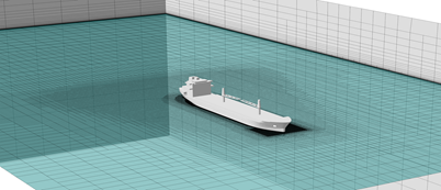
Marine simulations require careful attention to geometry handling, mesh structure selection, and quality standards to accurately capture complex fluid flow behaviors around ships and offshore structures.
Role of Geometry and Topology in Marine Meshes
Marine geometries present unique challenges for CFD mesh generation. Ship hulls feature complex curves, sharp edges, and multiple surfaces that intersect at various angles.
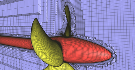
Your mesh quality depends heavily on how well you handle these geometric features. Leading edges on propellers and rudders require special attention to capture pressure gradients accurately.
Key geometric challenges include:
- Hull curvature variations
- Propeller blade surfaces
- Superstructure details
- Free surface interfaces
Topology affects how your meshing algorithm connects different geometric regions. Clean topology ensures smooth transitions between mesh elements.
Intersecting surfaces and non-conformal geometry can complicate mesh generation. Modern CFD meshing tools handle these issues, but clean geometry always produces better results.
Advanced CFD Meshing Approaches for Marine Applications
Modern CFD platforms offer sophisticated meshing strategies that address the complexity of marine geometries through different approaches:
Volume to Surface (V2S) Meshing
V2S is a robust and parallelized meshing approach that excels with complex marine geometries. This method supports unclean geometries with intersecting or non-conformal surfaces and doesn't require prior surface meshing.
Key advantages for marine applications:
- Handles complex ship superstructures without extensive geometry cleanup
- Produces both full hex and hex-dominant unstructured meshes
- Full hex meshes use hanging nodes for consistent hexahedral structure
- Hex-dominant meshes use tetrahedra to connect hex sections without hanging nodes
- Excellent for anisotropic refinement of free surfaces and atmospheric boundary layers
Surface to Volume (S2V) Meshing
S2V is a fault-tolerant mesh generator optimized for high-quality surface grids and viscous layers. While it requires relatively clean geometry, it delivers superior results for critical marine flow regions.
Benefits include:
- Generates unstructured quad-dominant surface meshes
- Creates either fully tetrahedral or hex-dominant volume meshes
- Produces anisotropic surface meshes ideal for leading and blunt edges
- Generates structured meshes perfect for cavitation prediction
- Significantly reduces cell count while preserving surface capture accuracy
Types of Meshes: Structured vs Unstructured
You have two main mesh types for marine CFD applications. Each offers distinct advantages depending on your simulation needs.
Structured meshes use regular patterns of hexahedral elements. They align well with ship hull surfaces and provide excellent accuracy for boundary layer capture.
These meshes work best for simple geometries. They offer predictable quality but require more setup time for complex shapes.
Unstructured meshes use triangular or tetrahedral elements with flexible connectivity. They handle complex marine geometries more easily than structured approaches.
Your mesh generation time decreases significantly with unstructured methods. They adapt well to irregular surfaces and multiple components.
Hybrid approaches combine both types. You get structured elements near walls for accuracy and unstructured elements in complex regions for flexibility.
Importance of High-Quality Meshes in CFD Simulations
Mesh quality directly impacts your CFD simulation accuracy and stability. Poor quality elements can cause solution errors or convergence problems.
Quality metrics you should monitor:
- Aspect ratio: Keep below 100:1 for most applications
- Skewness: Maintain under 0.8 for reliable results
- Orthogonality: Aim for angles close to 90 degrees
High-quality meshes capture boundary layers accurately. This is critical for predicting drag, lift, and pressure distributions on marine vessels.
Your computational efficiency improves with better mesh quality. Well-shaped elements require fewer iterations to reach convergence.
Mesh refinement in key areas enhances solution accuracy. Focus refinement near walls, free surfaces, and regions with high gradients.
Regular mesh quality checks prevent simulation failures. Use built-in quality tools to identify and fix problematic elements before running your analysis.
CAD Preparation and Feature Identification
Proper CAD preparation forms the foundation for successful marine CFD meshing. You must identify and address geometry issues before mesh generation to avoid solver problems and ensure accurate results.
Cleaning and Simplifying Geometry
You need to create water-tight geometry before starting the meshing process. This means your model must have no holes or gaps that could cause mesh generation failures.
Remove unnecessary details that don't affect flow physics. Small bolts, rivets, and minor surface features can complicate meshing without adding value to your analysis.
Simplify complex curved surfaces where possible. Sharp transitions and highly detailed areas create meshing challenges that slow down your workflow.
Check your model's scale and units before proceeding. Marine geometries often have mixed units that cause meshing problems. Convert everything to consistent units early in the process.
Export your geometry in formats that preserve surface quality. STL files work well for many CFD applications, but higher-quality formats may be needed for complex marine shapes.
Recognizing Critical Features for CFD Meshing
Identify leading and blunt edges on your marine geometry. These areas need special attention during mesh generation because they affect flow separation and pressure distribution.
Look for free surface regions where water meets air. These zones require refined meshing to capture wave formation and surface effects accurately.
Mark areas where boundary layers are critical. Hull surfaces, propeller blades, and rudders need fine mesh spacing near walls to resolve viscous effects properly.
Find regions with high curvature or complex topology. Propeller hubs, bow sections, and stern areas often have geometric complexity that demands careful mesh planning.
Locate interface boundaries between different components. These connections must be handled correctly to ensure proper flow communication between mesh zones.
Handling Gaps, Overlaps, and Intersections
Check for gaps between surfaces that should be connected. Even small gaps can cause mesh generation to fail or create incorrect flow paths in your simulation.
Remove surface overlaps where geometry intersects incorrectly. These create non-manifold features that confuse mesh generators and lead to poor quality cells.
Fix intersecting surfaces by trimming or modifying geometry. Marine models often have complex intersections between hull sections, appendages, and superstructures.
Use CAD repair tools to identify non-manifold edges automatically. These features appear where more than two surfaces meet at a single edge.
Verify geometric integrity after making repairs. Run geometry checks to confirm your fixes didn't create new problems elsewhere in the model.
Advanced Refinement Strategies for Marine Applications
Surface Refinements
Optional surface and local refinement capabilities can increase mesh resolution in target areas. Mesh uniformity, edge proximity, and local curvature all determine whether the surface mesh requires further refinement.
Global Settings Approach Refining each surface individually and checking proximity between surface edges can be tedious when working with complex geometries having multiple surfaces. Global settings help refine entire geometries efficiently - perfect for ship superstructures where you need consistent quality across all surfaces.
Volume Refinements
Volume refinement proves especially useful for marine design studies when refinement targets specific volumes like:
- Free surface regions
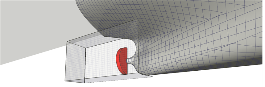
- Actuator disk regions around propellers
- Wake zones behind vessels
- Interface boundaries between different fluid domains
When modeling propeller wakes, create refinement zones around actuators using rectangular boxes. The area beyond these regions (typically the free surface) should also be refined but with different refinement levels to balance accuracy and computational cost.

Viscous Layer Insertion Techniques
Modern CFD platforms offer three main techniques for viscous layer insertion:
1. Inflation Method
- Pushes Euler cells away from solid boundaries for viscous layer insertion
- Maintains good adjacent volume ratio
- Layers may be irregular and might not achieve user-defined height
- Best for general marine applications
2. Extrusion Method
- Trims Euler cells close to solid boundaries and reconnects them to far field
- Produces viscous layers of ideal height with perfect far-field mesh
- Ensures first viscous layers start fully normal to walls
- Ideal for cavitation prediction on propellers and hydrofoils
- Reconnection layer may contain various cell types
3. Splitting Method
- Fastest viscous layer insertion by splitting first buffer cells
- Used only for extremely complex geometries
- Does not guarantee maintained adjacent volume ratio
- Provides quick solutions when other methods struggle
Despite individual limitations, modern platforms can achieve 100% viscous layer coverage around complete marine geometries.
Anisotropic Refinement for Marine Applications
Anisotropic refinement dramatically improves computational efficiency while maintaining accuracy:
- V2S approach: Excellent for anisotropic refinement of free surfaces and atmospheric boundary layers, applied at the end of mesh generation
- S2V approach: Produces anisotropic surface meshes for leading and blunt edges, drastically reducing cell count compared to isotropic cells while preserving surface capture
The structured meshes produced using S2V are particularly ideal for predicting cavitation on marine propellers and hydrofoils.
Adaptive Mesh Refinement in Flow Solvers
When designing new marine vessels, predicting flow fields beforehand and determining where mesh cells are necessary is challenging. Traditional approaches often result in over-resolution and significant computational overhead.
Adaptive Mesh Refinement (AMR) solves this by adjusting the mesh during simulations, ensuring cells are only used where needed. This approach:
- Captures all relevant physics with only a fraction of the cells
- Completes simulations 2X faster or more, especially for unsteady flows
- Dynamically adapts to solve complex marine physics
- Addresses unprecedented conditions automatically
AMR technology in modern flow solvers can handle the various challenging conditions in marine applications and dynamically adapt meshes to resolve the involved physics effectively.
Best Practices for Marine CFD Meshing
- Start with the cleanest geometry possible - even fault-tolerant meshers perform better with clean CAD
- Choose your meshing approach based on geometry complexity - V2S for complex/unclean geometries, S2V for high-quality requirements
- Plan refinement strategies early - identify critical flow regions before meshing
- Leverage global settings for complex geometries with multiple surfaces
- Use appropriate viscous layer techniques based on your accuracy requirements
- Consider anisotropic refinement to reduce computational costs
- Implement adaptive mesh refinement for unknown flow fields
Modern CFD meshing technology has transformed marine CFD from a time-intensive process to a streamlined workflow that can handle the most complex vessel geometries while maintaining the accuracy needed for reliable design decisions.